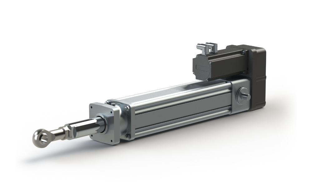
Actuator
Design tool

Orientation & Application
Load cycle
Motion profile
Actuator selection
Configuration:
Mass: i
Stroke: i
Coefficient of friction (µ): i
Tilt angle: i
0°=horizontal, 90°=vertical
Process force: i
Direction of the process force: i
Cycle time calculation
Stroke time in one direction: i
Break after each stroke: i
Number of strokes per load cycle: i
Cycle time:
Lifetime calculation
Number of load cycles per hour:
maximum number:
Operating hours per day:
Days per year:
Years:
Total number of load cycles:
Required lifetime:
No entries are required here, please check the calculated load cycle and then click Next to go to the preselection of suitable cylinders.
Trapezoid profile according to 1/3 rule
| Positioning way | m |
| Positioning time | s |
| max. Speed | m/s |
| Acceleration | m/s² |
| tb | s |
| tk | s |
| tv | s |
| t Break | s |
Select motor mounting
Actuator capacity
>=50%
Hubzylinder Auslegungstool
Configuration code: i

Ihre eingegebenen Kontaktdaten:
Company:
Name:
Mailadresse:
Ihre Projektreferenz:
Ihre Anfrage können Sie uns an office@atp-antriebstechnik.at senden
Calculation inputs
| Mass | kg |
| Stroke | mm |
| Coefficient of friction (µ) (µ) | |
| Inclination angle | ° |
| Process force | N |
| Force direction of the process force | |
| Stroking time in one direction | s |
| Pause after each stroke | s |
| Number of strokes per load cycle | |
| Number of load cycles per hour | |
| Operating hours per day | |
| Days per year | |
| Years |
Motion profile
Calculation results
| Fmax Application | N |
| required lifetime | km |
| max. lifting speed | mm/s |
Motor utilization
Please select actuator beforehand
Ausgewählter Hubzylinder
Motor utilization
| Teff (RMS) | Nm |
| Tmax | Nm |
| Rotations Ø | rpm |
| max. rpm | rpm |
matching actuators
Expertenansicht
ATP Antriebstechnik GmbH & Co KG assumes no liability for any incorrect entries. In case of an order, we check your configuration for plausibility and send you an alternative proposal if necessary.


