Dimensioning of electric lifting cylinders with ball screw
For many applications in mechanical engineering and automation with special requirements for performance, precision or duty cycle, electric lifting cylinders with ball screw are the ideal drive solution. However, the prerequisite for this is the correct dimensioning for the specified loads and the required service life.
If these data are known, an exact service life calculation of the ball screw spindles as well as an optimal design of the other components such as motor and transmission can be carried out.
Step by step to the correct spindle dimension

Properties
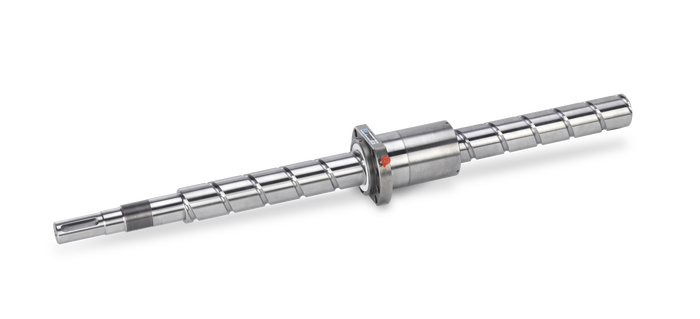
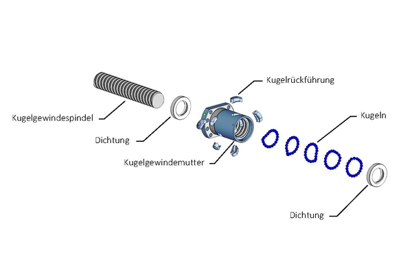
The technical properties and terms for ball screws are defined in DIN 69051. The ball screw is a mechanical system consisting of a ball screw shaft and a ball nut with continuously rotating rolling elements for converting a rotary movement into a longitudinal movement or vice versa. The rotation about a fixed axis is thus converted into a linear movement by a defined pitch of the thread.
A high degree of efficiency is achieved by the rolling movement of the balls between the shaft and the nut. According to the requirements for the respective application, a distinction is made between positioning and transport ball screw drives. Thereafter, the design parameters such as the preload, tolerance class and path deviation are determined. The load capacity and the maximum speed are determined by the raceway profile, the number of ball revolutions within the ball nut, the design of the return system and the spindle pitch.
Lifetime calculation and selection
For the selection of the required ball screw drive, the loads and the desired service life must be known or determined as follows.
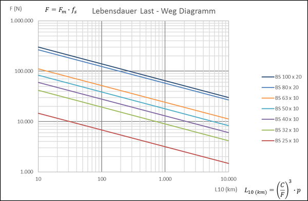
In the case of variable load and speed, the equivalent dynamic load Fm is calculated from the individual loads and speeds with the time components of the individual phases.

The nominal service life L10 of ball screws is calculated in accordance with DIN ISO 281 as in the case of rolling bearings.
The required service life in kilometers L10 (km) results from the stroke distance per load cycle times the number of load cycles in the observed period of time.

Extract from the product catalogue
| Ball screw designation | Nominal diameter | Gradient | Ball diameter | Number of rounds | Dynamic load capacity | Static load capacity |
| KGT | do (mm) | p (mm) | d (mm) | z | C/N | C0 /N |
| BS 25 x 10 | 25 | 6 | 3.97 | 3 | 17,400 | 30,500 |
| BS 32 x 10 | 32 | 10 | 6.35 | 5 | 41,800 | 73,000 |
| BS 40 x 10 | 40 | 10 | 6.35 | 5 | 60,000 | 124,000 |
| BS 50 x 10 | 50 | 10 | 6.35 | 6 | 83,000 | 188,000 |
| BS 63 x 10 | 63 | 10 | 7.14 | 6 | 112,000 | 313,000 |
| BS 80 x 20 | 80 | 20 | 12.70 | 5 | 213,000 | 516,000 |
| BS 100 x 20 | 100 | 20 | 12.70 | 4 | 239,000 | 687,000 |
With the help of the force path diagram, the pre-selection of a suitable ball screw can be made easily and quickly.

For the selection of the electric lifting cylinder and the exact calculation for the given requirements, we recommend the following procedure:
- Select design for the existing installation situation
- Determine size with the selected ball screw
- Checking the permissible spindle speed
- Checking the permissible compressive load (buckling)
- Calculation of the drive torque and the drive power
- Selection of the engine speed and, if necessary, the required gear reduction


